1. Preparation of the holes in the housing.
This step should be one of the first undertaken. Sawdust and metal debris generated during cutting and drilling is most easily removed without affecting later components. Metal filings which interfere with electronic equipment (e.g. PLC or power supplies) can lead to short circuits and damage with the potential to cause danger to users.
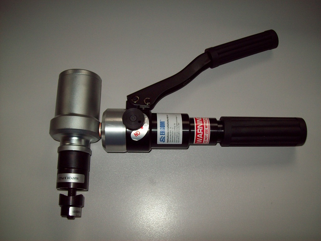
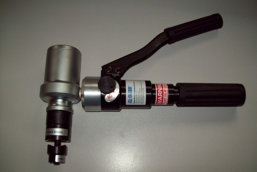
To complete the preparation of circular holes, use a hydraulic or screw punch.
Screw punch on the picture below.

Easier to use hydraulic punch .
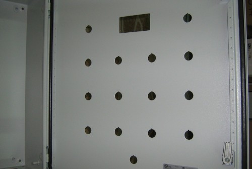
Holes in other shapes can be made using a jigsaw with a suitable blade for cutting metal. Some images of cabinets with prepared holes.
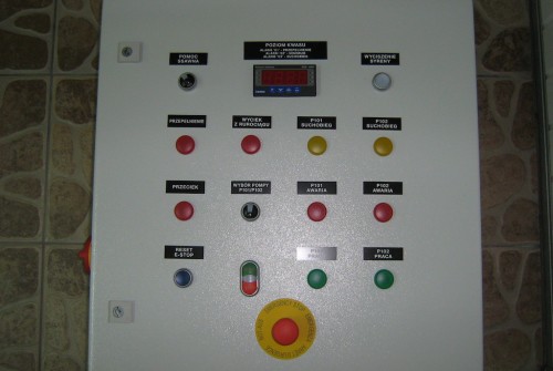
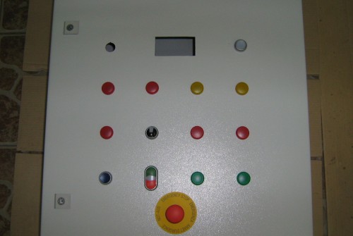
2. Installation of control and signalling equipment on the cabinet door.
Use the prepared holes to install controls and switches. Components which are sensitive to shock or which have delicate displayed should be installed later to avoid possible damage.
Cabinets door from the outside.
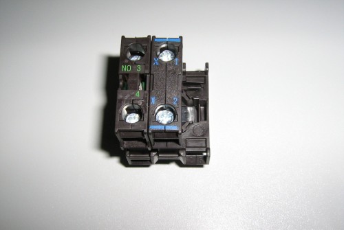
Control equipment without fixing adapters.

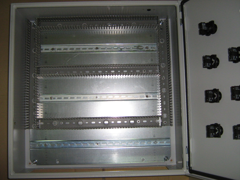
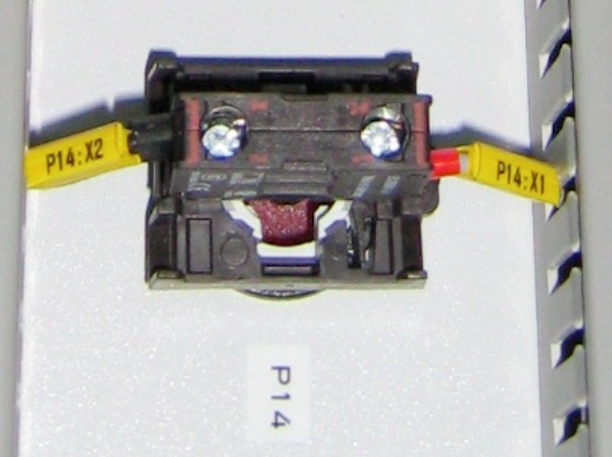
Cabinet door from the inside. Fixing adapters used to mount contacts and indicator lights.
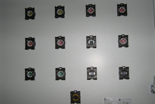
Usually each fixing adapter allows the installation of up to three elements, namely two contacts and one light.
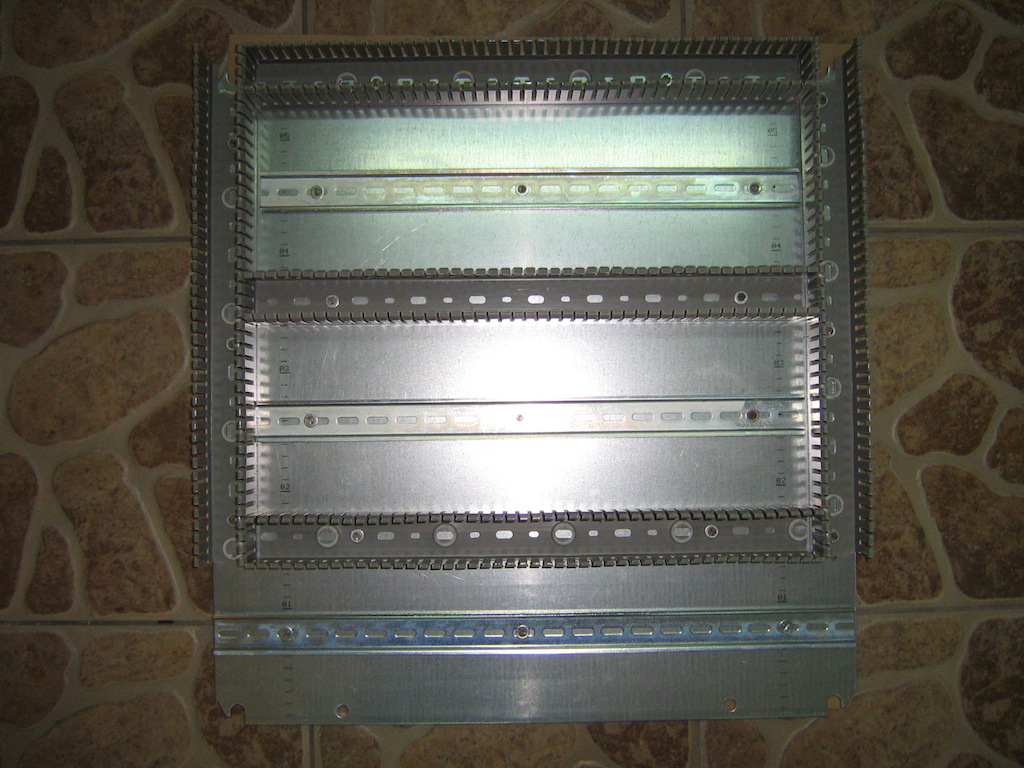
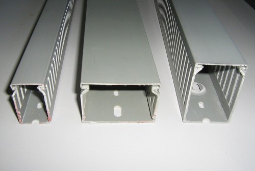
3. Installation of cable ducts and rails.
Use the mounting plate to position perforated ducts (available in a range of sizes) and DIN rails (usually a standard 35mm in size). Cable ducts and rails are usually available in two metre sections should be cut to the required size.
Perforated cable ducts available in range of sizes (25 x25, 25 x 40, 40 x60, 60 x60 mm, etc).
Cable ducts and rails can be fixed to the mounting plate by bolts or screws as appropriate.
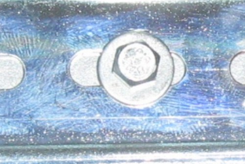
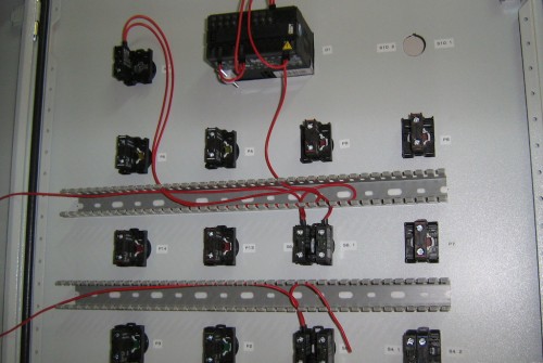
Mounting plate with attached cable ducts and DIN rails.
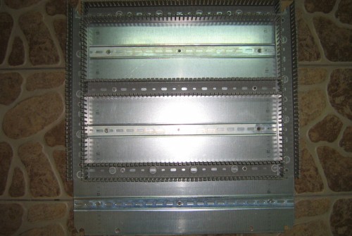
Close view to the bottom of the plate.
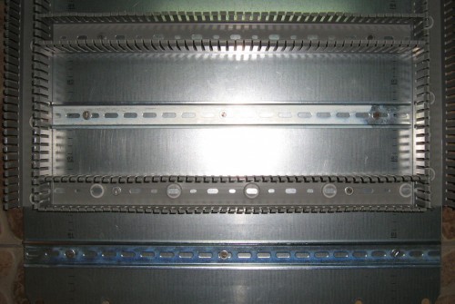
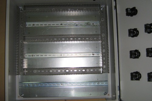
The prepared mounting plate should be placed securely in the cabinet.
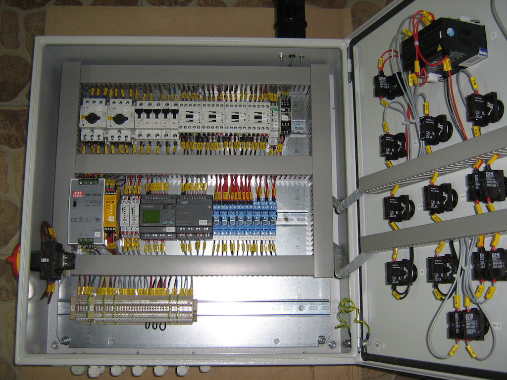
4. Installation of components.
Standard electronic components will snap to the DIN rail. Larger devices such as variable frequency drives are safer to install by screwing directly to the mounting plate.
5. Electrical connections.
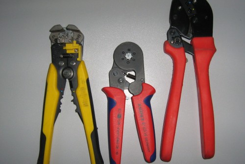
For this process, ensure you have the required stripping and crimping tools. When cutting wires to length, it is safe to leave some excess for each device. This allows slight adjustment of component positions without re-running new wires.
Each end of the wires should be crimped with ferrules of the appropriate length and diameter. Some electrical design requires two wires to be connected in a chain, and the appropriate twin ferrules should be used. A twin ferrule and two single ferrules.
Tools for working with a new panel: stripping, crimping sleeves, and crimping lugs.
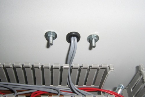
Securing wires passing through the walls of a cabinet using rubber sleeves.
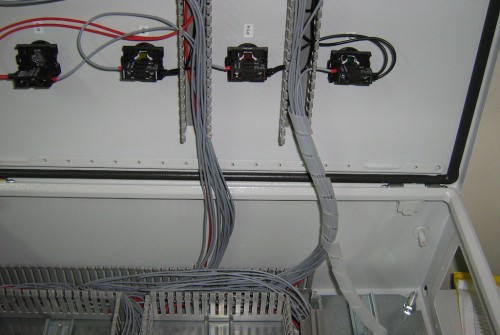
Small perforated cable duct can be used to guide wires to components mounted on the cabinet door. This can be affixed with double-sided tape once the surface has been prepared.
Wire harnesses which connect components on the cabinet doors can be grouped using polyamide spiral wraps for flexible, mobile, connections.
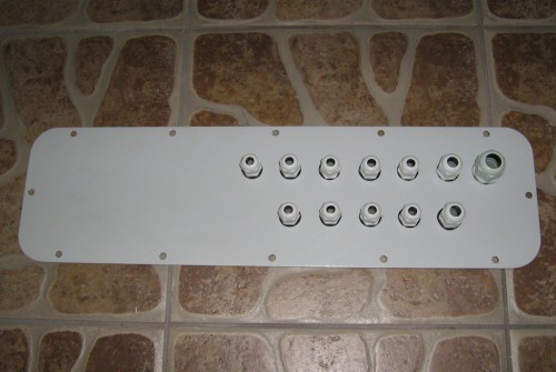
7. External connection using a plate with cable glands.
In general, any connection to external electrical equipment is carried out via a plate located at the bottom of the cabinet. One of the last operations is to prepare the holes for cable glands in this lower plate.
Plate with installed cable glands.
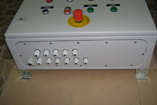
Completed cabinet with installed glands.
View of the finished cabinet door. Engraved plates inform the user of the device descriptions.